- +8618937185591
- +8618937185591
- ec19@zkcorp.com
- +8618937185591

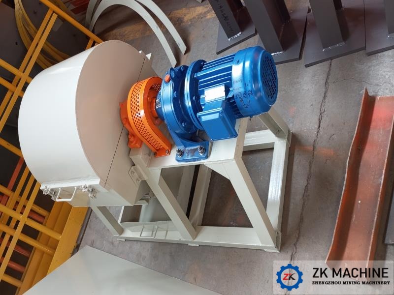
The Φ600×700mm ball mill is suitable for batch feeding and is a new type of energy-saving ball mill developed by incorporating the latest domestic ball mill technology. It significantly improves production capacity and grinding efficiency. The fineness of this product is more uniform, while also saving energy.
The fineness of grinding material can be controlled by adjusting the grinding time. This product has low investment, energy savings, novel structure, simple operation, safe use, and stable and reliable performance compared to similar products.
1. Working Principle
This ball mill is a center driving mode, batch discharge type. When the cylinder rotates, the material is highly crushed due to the impact and grinding from hard grinding media.
After stopping the grinding, open the inspection door cover and use the control box to jog to turn the grinding door directly above. Replace with a discharge grinding door and tighten all connecting components, then cover the inspection door cover. Start the ball mill and perform rotary unloading. The crushed material is discharged through the discharge mill door and the discharge hood, and enters the receiving hopper. The materials can be transported out in batches through the receiving hopper.
After unloading is completed, open the inspection door cover and use the control box to jog to turn the unloading grinding door directly above. Remove the discharge mill door and add material into the mill. After the feeding is completed, cover the abrasive grinding door and tighten all connecting parts. Cover the inspection door and start the ball mill for grinding.
3. Technical Parameters
No | Item | Unit | Specification | Note | |
1 | Model | mm | Φ600×700 | ||
2 | Type | Dry batch type | |||
3 | Effective volume of shell | m³ | 0.15 | ||
4 | Max. loading of grinding media | t | 0.3 | ||
5 | Revolution Shell | r/min | 41.1 | ||
6 | Feeding size | mm | ≤20 | ||
7 | Moisture | <3% | |||
8 | Processing capacity | L/ batch | 60 | ||
9 | Gear motor | Speed ratio | 35 | Explosion-proof motor | |
Rotating speed | r/min | 41.1 | |||
Power | kW | 5.5 | |||
4. Structure and Features
The ball mill mainly consists of the main bearing device, rotation part, transmission device, mill base frame, a discharge cover, a flexible connection, and a feeding hopper.
(1) Main bearing device: The main bearing bears not only the weight of the mill and grinding media but also the torque during rotation. The main bearing of this mill is a self-aligning roller bearing, which has a low friction coefficient and is easy to maintain. Lithium-based grease is added to protect the bearings.
(2) Rotation part: It is mainly made of high-quality carbon steel plates that are welded together to form the shell and two end caps connected by bolts. The shell is equipped with liners to protect it and the end covers. For checking and replacing the mill's components and adding grinding media, there is a maintenance door on the shell. Before each work, a certain amount of nitrogen gas needs to be introduced into the abrasive through the nitrogen inlet.
(3) Transmission device: The main shaft is driven by a gear motor through a coupling to rotate the ball mill. To ensure safety, a coupling guard is also provided.
(4) Mill base frame: After the overall welding is completed, integrated processing is carried out to ensure the machining and fitting precision and geometric tolerances of each part, effectively improving the installation accuracy and reliability of the entire machine.
(5) Discharge Cover: The inspection door is easy to open, facilitating the replacement of the mill door during loading and unloading. The cover has good sealing performance, allowing material to be discharged while the mill is rotating, and reducing material accumulation in dead corners after grinding. This ensures orderly discharge of materials while maintaining a clean and tidy working environment.
(6) Receiving Hopper: The receiving hopper is equipped with a flexible connection, which can receive the material discharged from the discharge slide valve while ensuring no material leakage. At the same time, a movable caster is installed at the bottom of the receiving hopper, allowing the material in the hopper to be easily moved to the desired position, thereby reducing the labor intensity of workers.
Fast, professional and reliablewe provide you with services throughout the product ...

Email
ec19@zkcorp.com

Whatsapp
+8618937185591
Fast, professional and reliablewe provide you with services throughout the product . you with services t


